Operation 1
In this operation, the aircraft performs a mission consisting of a runway for the approach phase in Fixed-Wing (FW) flight configuration and a closed loop passing through all flight phases.
The performance of the aircraft in each of these phases and the transitions between phases that are triggered, are explained below.
Initial and Standby
In these flight phases all actuators are disabled. The guidance program does not send any commands to the actuators, so the charts do not show any data.
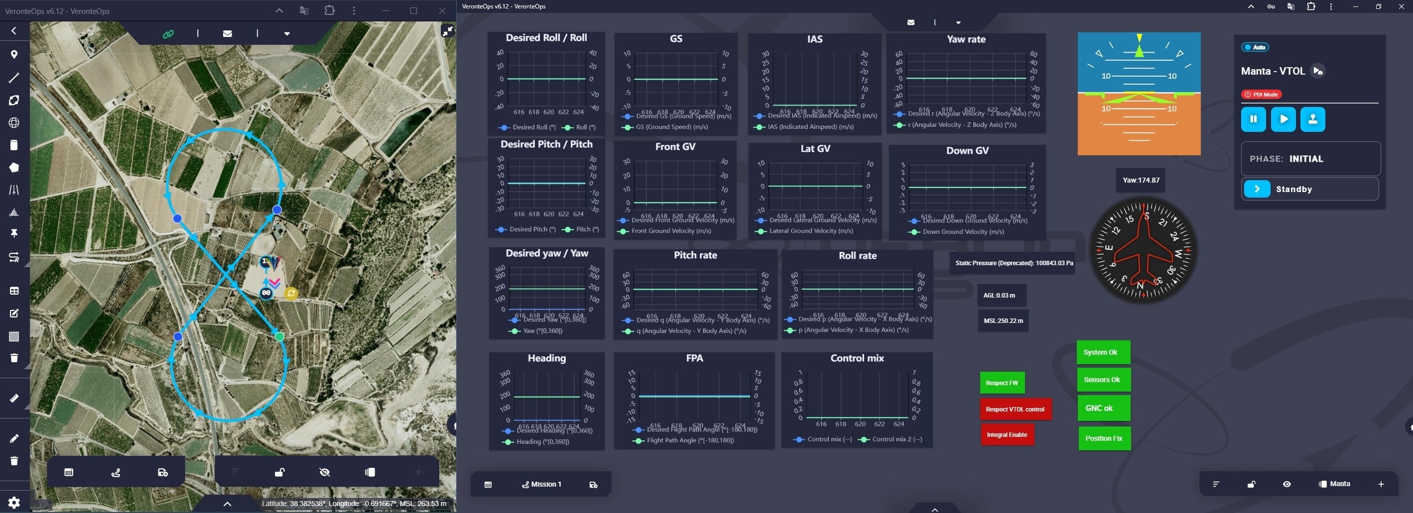
Operation 1 - Initial flight phase
Armed
In this flight phase, the four motors providing the thrust increase the RPM to 25%. This increase, as explained, has been defined in the block programs.
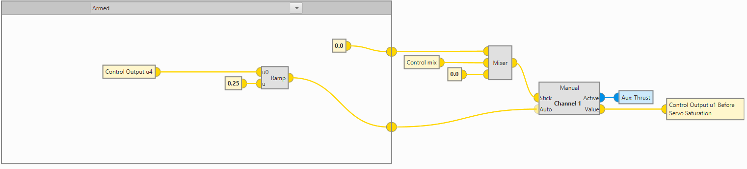
Operation 1 - Armed in Block Programs
This activation of the motors can be easily visualized with the gauges added to the workspace.
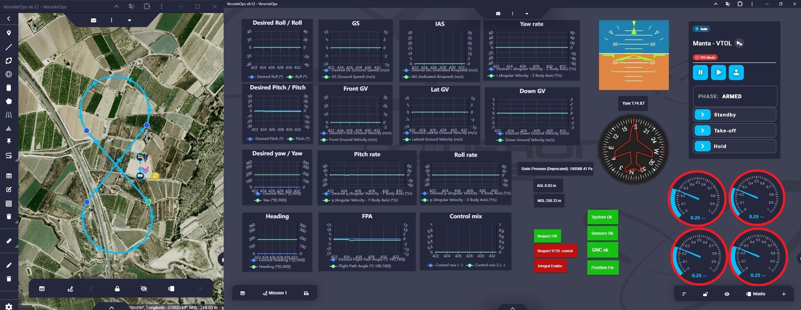
Operation 1 - Armed flight phase
Take-off
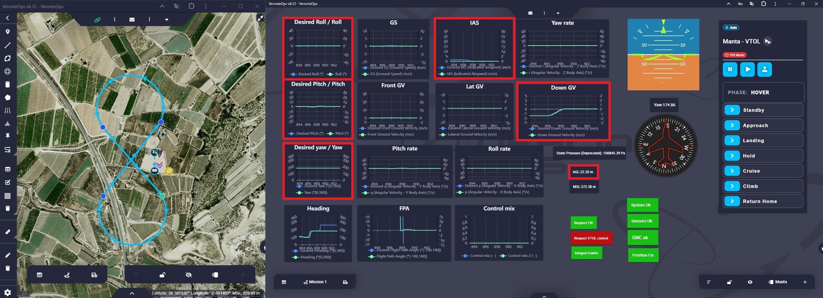
Since Take-off phase is performed with the aircraft in quadcopter flight configuration, the control variable is the Down Ground Velocity (DGV).
The aircraft performs a take-off at a DGV of 1.5 m/s.
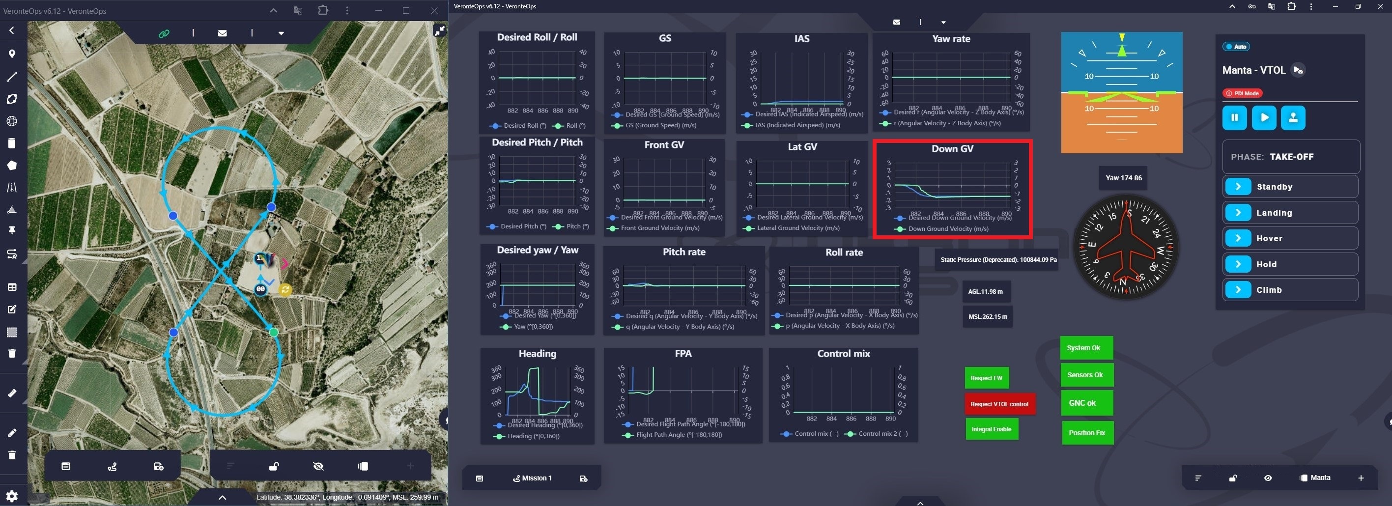
Operation 1 - Take-off flight phase
Once the aircraft reaches 20 meters (AGL), Autopilot 1x transitions to the Hover flight phase. This automation has been explained in the Automations - 1x PDI Builder configuration section.
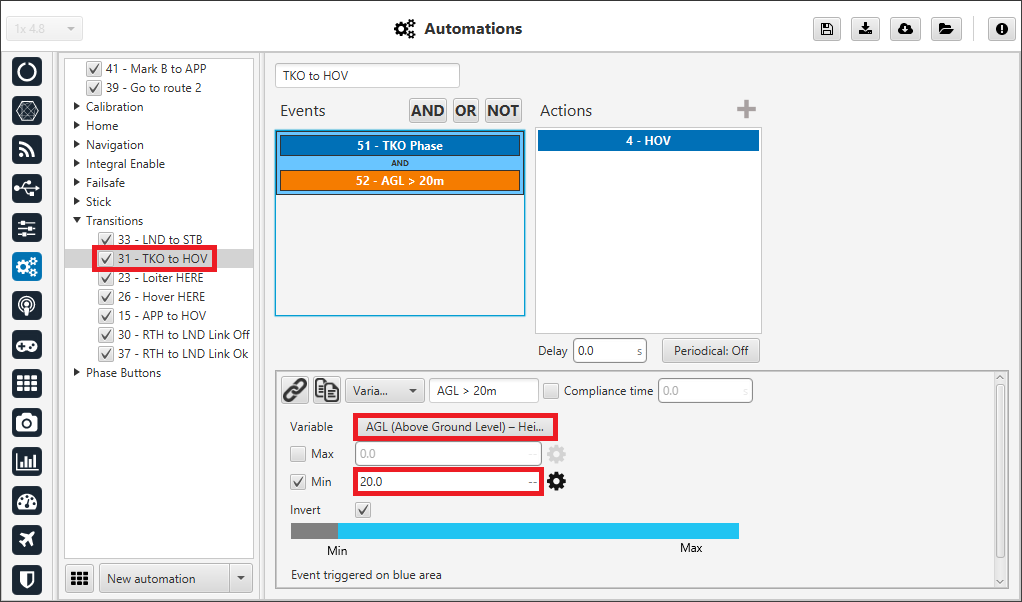
Operation 1 - TKO to HOV automation
Hover
In this flight phase, Veronte Autopilot 1x stabilizes the 3D position, so the aircraft attitude control variables (Desired Pitch, Desired Roll, Desired Yaw), Desired Down Ground Speed and Desired IAS variables are null and constant.
Operation 1 - Hover flight phase
Cruise
When the operator commands Autopilot 1x to swtich to the Cruise flight phase, a path to the mission point defined as Start Route is automatically generated.
To switch from Hover to Cruise, the aircraft changes the flight configuration from quadcopter to FW. This change can be represented by plotting the Control mix variable on a chart.
In this workspace, two labels have been added to show the behavior of the PID controllers for quadcopter and FW control:

In this flight phase, the control variables for attitude are: Desired Pitch, Desired Roll and Desired Yaw. And for aircraft speed: Front Ground Velocity and Lateral Ground Speed.
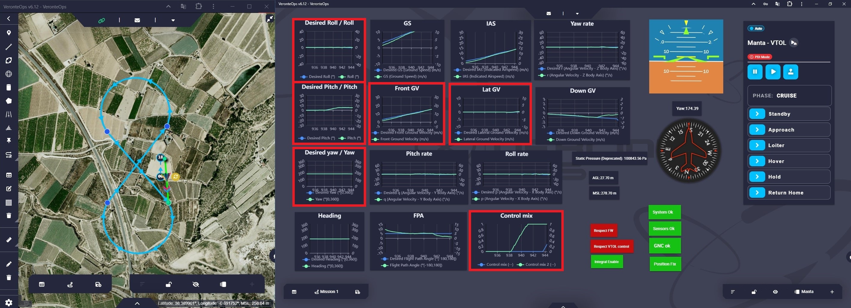
Operation 1 - Cruise flight phase
Veronte Ops allows users to visualize the aircraft trajectory during the mission. For more information, visit the Platform icon - Veronte Ops configuration of the Veronte Ops user manual.
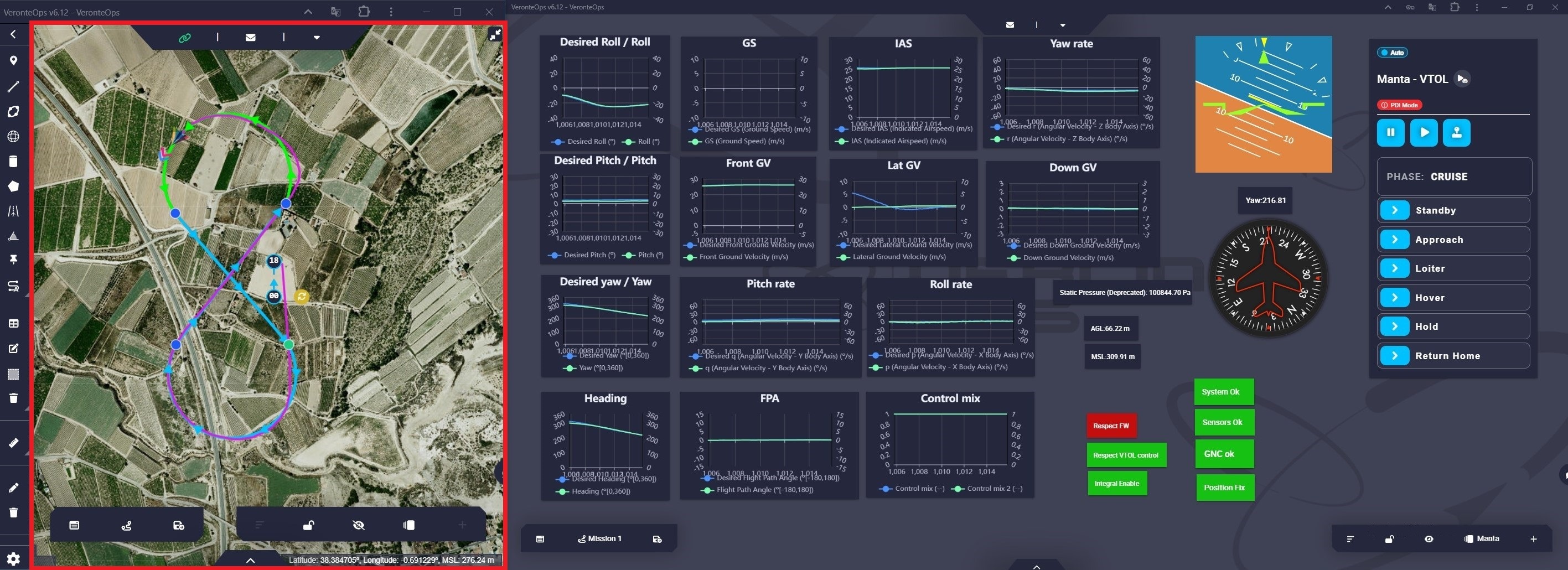
Operation 1 - Trajectory in cruise flight phase
Note
In this operation, the aircraft will remain in the Cruise phase until a phase change is commanded.
Loiter
Note
Loiter phase can only be entered manually by the user from its phase button on the Veronte Panel.
When the operator commands Autopilot 1x to switch to Loiter flight phase, a circular path is generated around a point, which is the current position where the aircraft is at that moment.
Note
The aircraft follows this route until another phase change command is given.
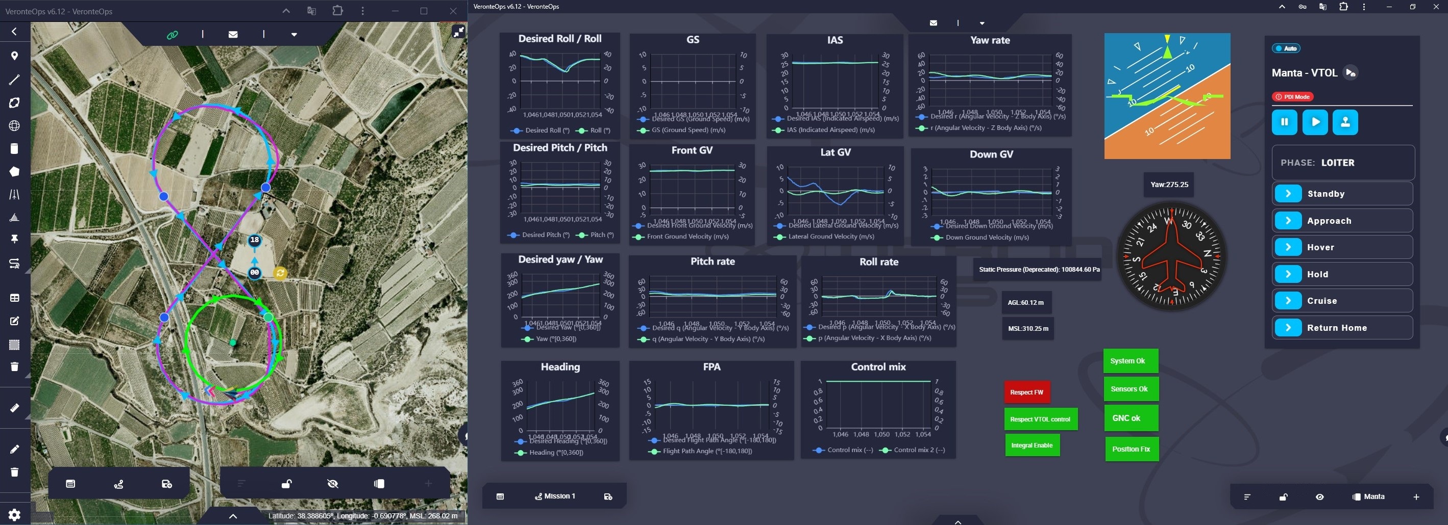
Operation 1 - Loiter flight phase
The path configuration for Loiter is defined in the following automation:
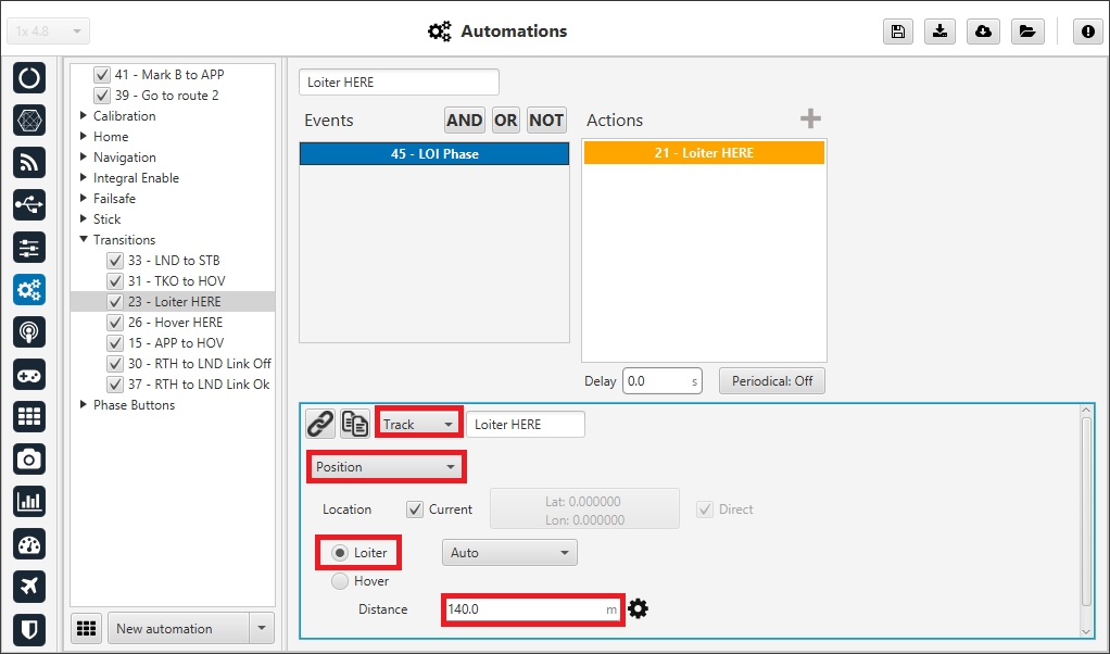
Operation 1 - Loiter here automation
For more information, visit the Automations - 1x Air configuration of this manual.
Hold
In this flight phase, the aircraft attitude and vertical velocity are stabilized. The control variables Desired Pitch, Desired Roll, Desired Yaw and Desired Down Ground Velocity are null and constant.
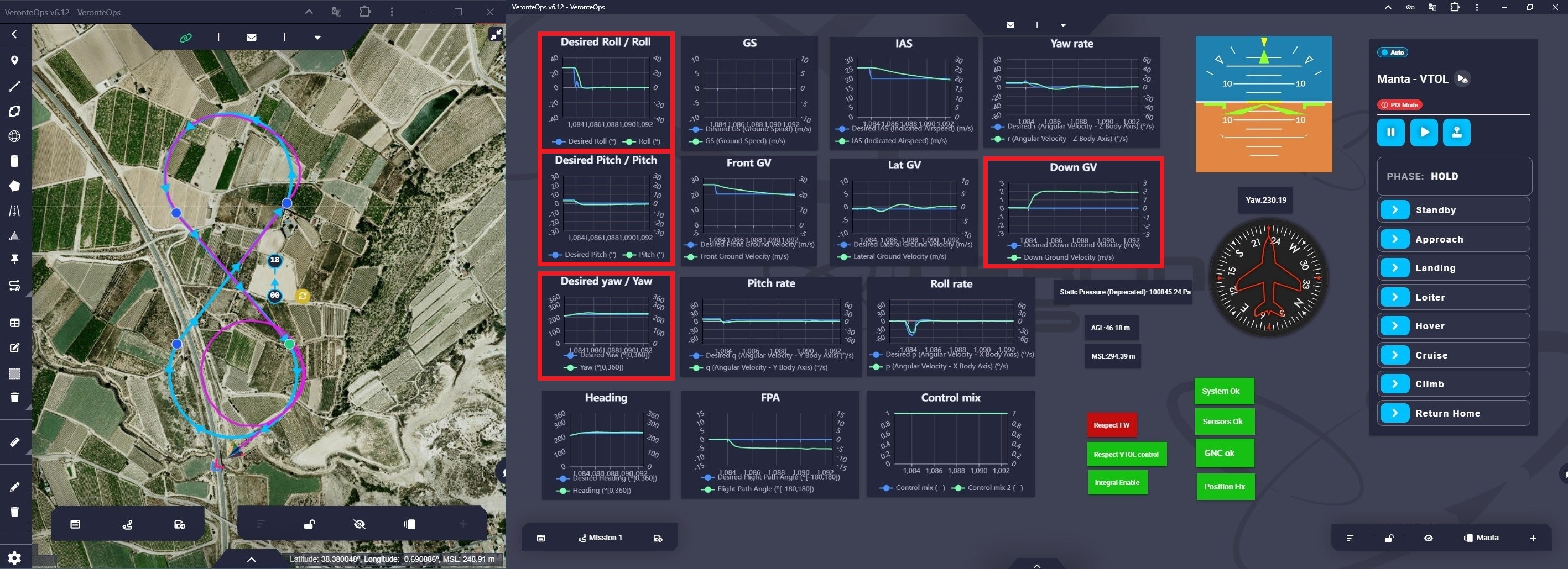
Operation 1 - Hold flight phase
Approach
When the aircraft enters the Approach flight phase, the guidance program automatically generates a path to the runway. This path will have enough distance for the aircraft to lose altitude and perform the approach correctly.
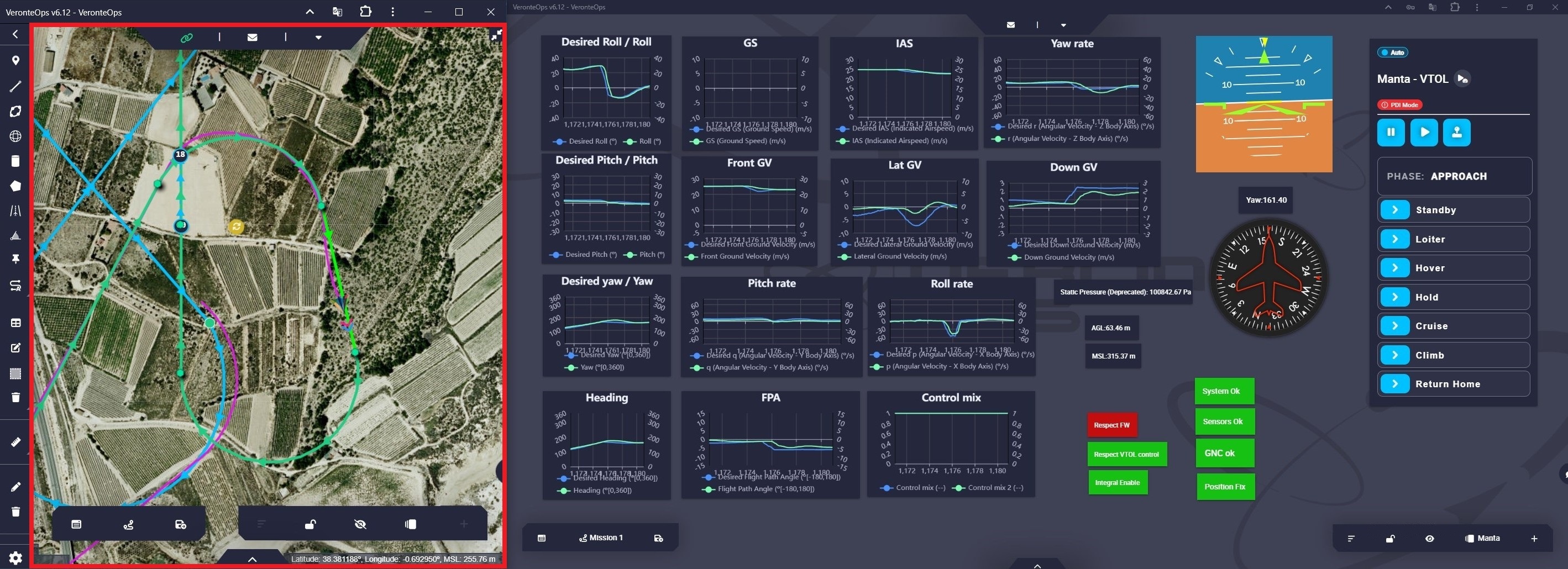
Operation 1 - Approach flight phase
Approach phase ends on the runway, where the aircraft transitions to the Hover flight phase.
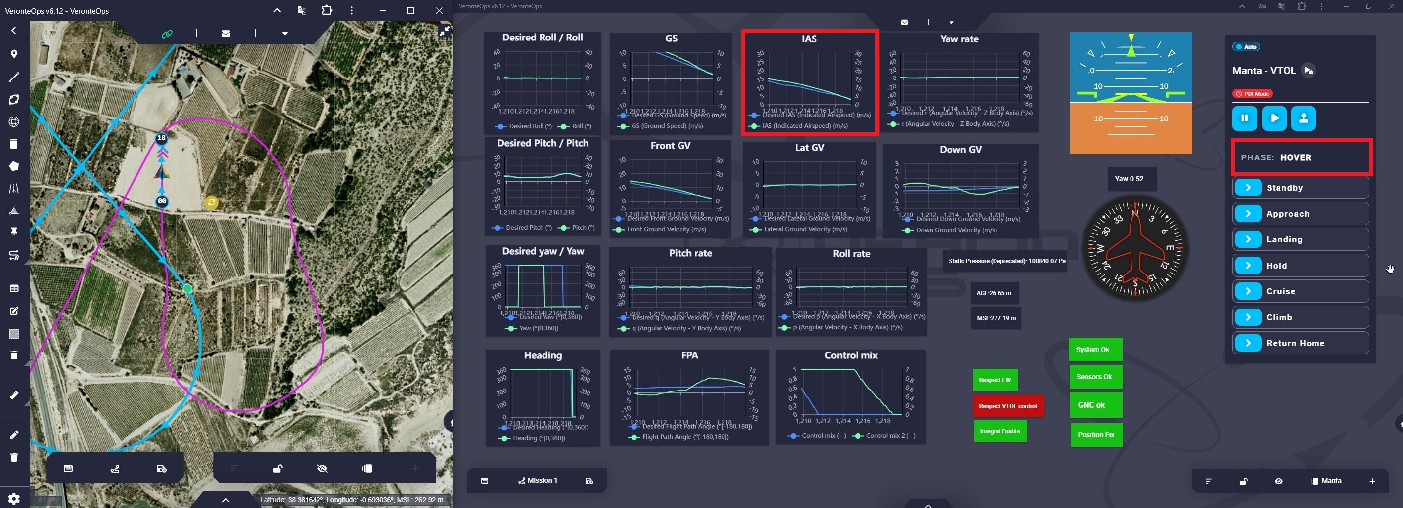
Operation 1 - Approach to Hover transition
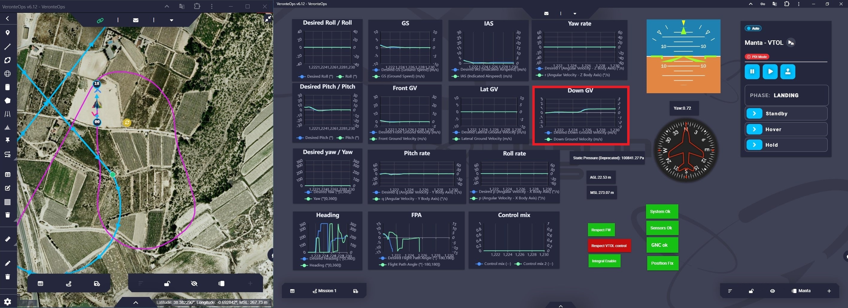
The automation that enables the transition from the Approach phase to the Hover phase has been defined in the 1x PDI Builder configuration:
Operation 1 - APP to HOV automation
For more information, visit the Automations - 1x Air configuration section of this manual.
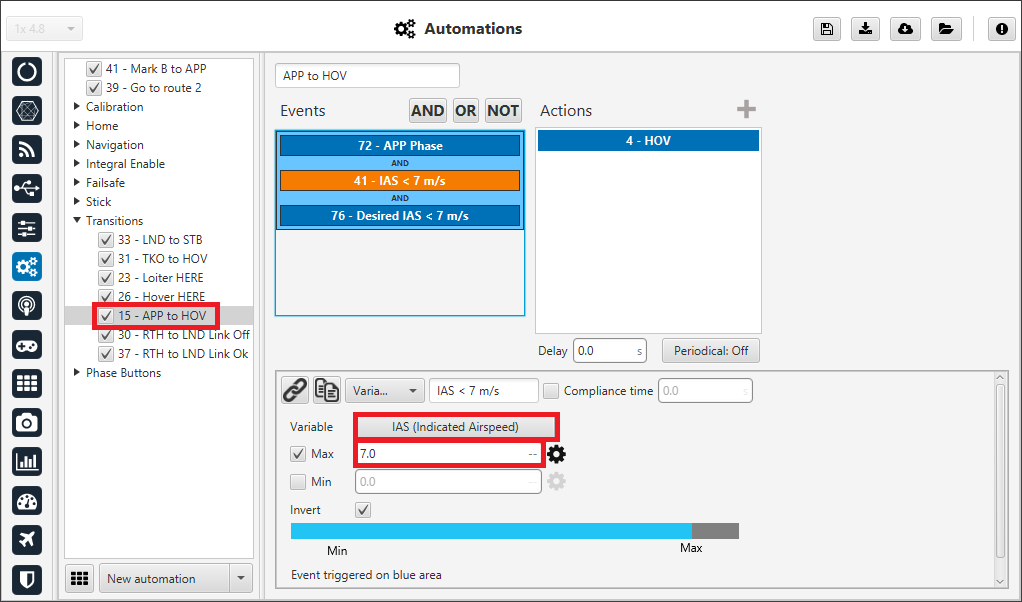
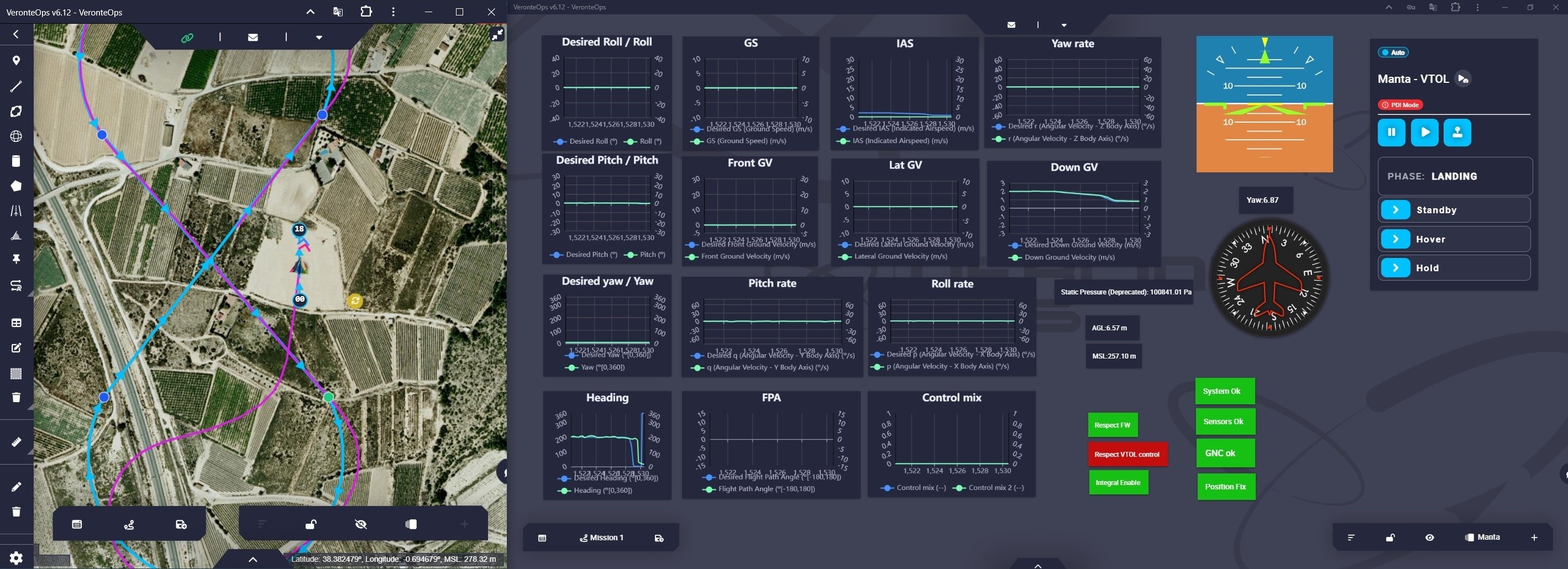
Landing
The control variable for the Landing phase is the Desired Down Ground Velocity:
Operation 1 - Landing flight phase
At the end of the Landing phase, the aircraft enters the Standby phase.
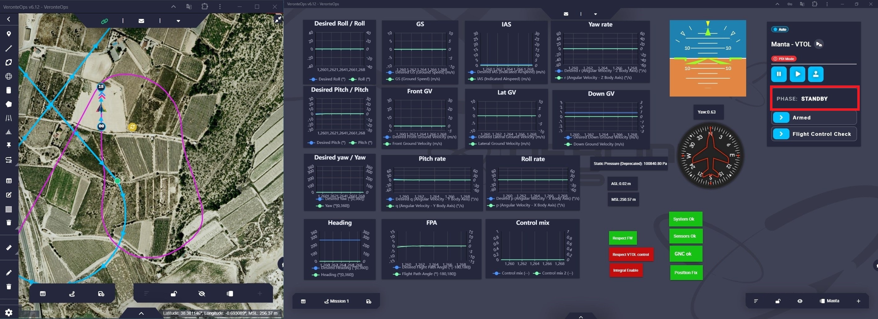
Operation 1 - Landing to Standby transition
The automation that allows the transition from the Landing phase to the Standby phase has been defined in the 1x PDI Builder configuration:
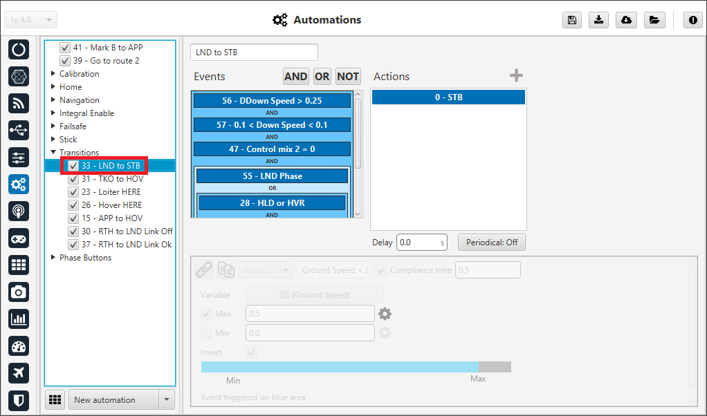
Operation 1 - LND to STB automation
For more information, visit the Automations - 1x Air configuration of this manual.
Return to Home
When the aircraft enters the Return to Home phase, the guidance program automatically generates a path to the point defined as Home.
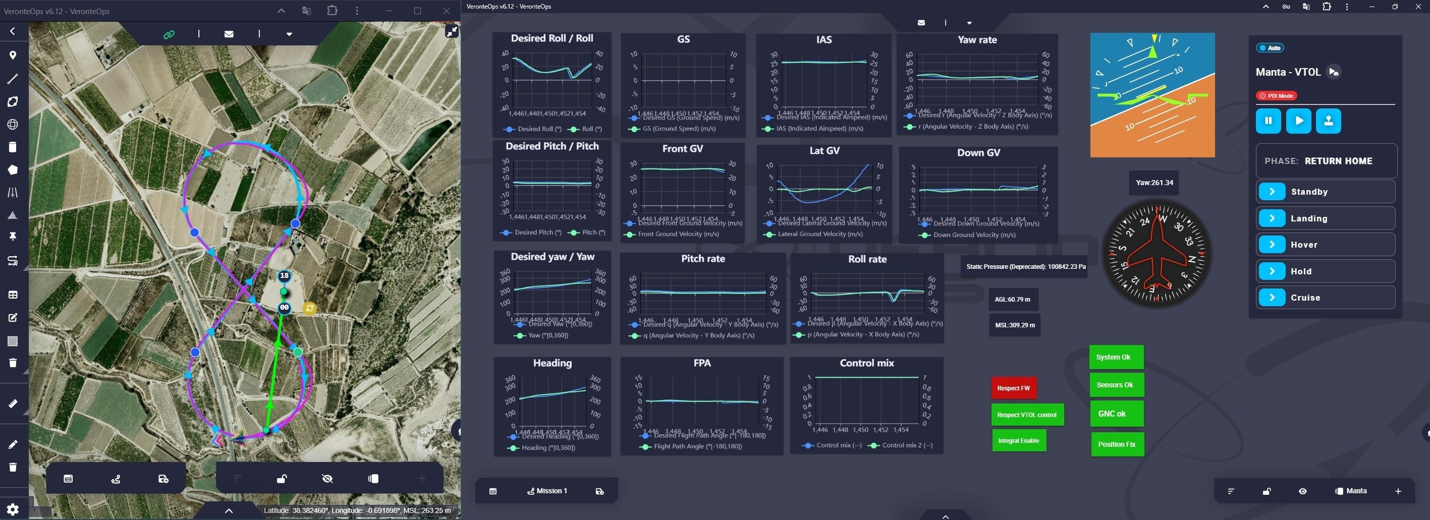
Operation 1 - Return to Home flight phase
This flight phase ends at the Home point, where the aircraft passes to the Landing flight phase.
Operation 1 - Return to Home to Landing transition
The automation that enables the transition from the Return to Home phase to the Landing phase has been defined in the 1x PDI Builder configuration:
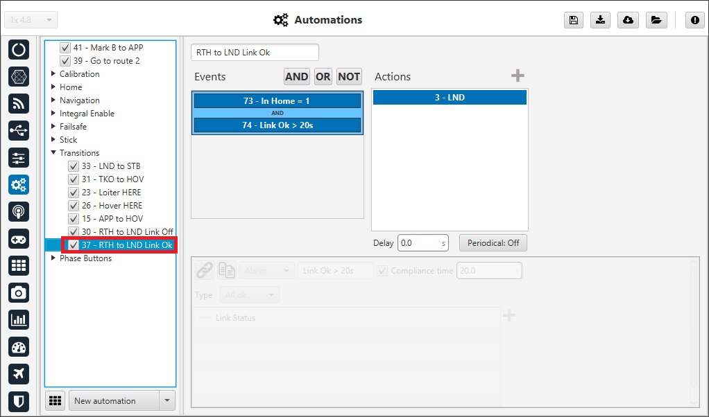
Operation 1 - RTH to LND automation
For more information, visit the Automations - 1x Air configuration of this manual.